
A Wide Field of View High Resolution Compact Virtual Reality Display
by Eric Howlett — May 19, 1992
Society for Information Display Symposium — Boston Convention Center
Abstract
In designing remote vision systems for human operators, two different features of the human eye should be considered:
- the very wide field of view of the eye permits secure and rapid orientation and the avoiding of obstacles;
- the high central (foveal) acuity of the eye permits fine discrimination.
A capable head-mounted display will not limit either of these human eye features more than absolutely necessary, LCDs show promise for reasonable cost and weight, but the small number of pixels available now and in the foreseeable future means a necessary limitation of the field of view or of the central acuity, or of both, if only one LCD is used per eye.
The best available compromise using only one LCD is embodied in the LEEP optics, which use a radial compression format to provide a very wide field with minimum loss of resolution at the center.
Radial image compressing optics are used increasingly to map a real or computer generated environment into a compact format for wide angle stereoscopic viewing. In the early 1980's the LEEP still photography system and the IMAX cinema systems for the OMNIMAX theaters used such compression. Evans and Sutherland has used it in simulation systems. In 1985 workers at NASA Ames research Center first used LEEP lenses with LCDs in head mounts for the VIEWS system, which demonstrated "immersive" Virtual Reality at reasonable cost. In 1989, systems based on LEEP optics and LCDs were offered commercially by POP-OPTIX LABS (now LEEP Systems, Inc.) and then by VPL, Inc. and others. LEEP optics have since become a de facto industry standard.
To improve on that standard, LEEP Systems, Inc. has undertaken two developments. The first simply increases the lateral field of view by twenty-five degrees (the CYBERFACE2); the second adds an optical high-resolution insert. Because the insert is added optically in the head-mount, the smaller the insert, the sharper its detail.
2. INTRODUCTION
2.1. Background
For much of the last decade we at LEEP have been looking at a kind of image that, until recently, very few people have seen. The images are stereoscopic and very wide angle; they are both still photographs and moving video; at the beginning, they were only photographs, because there was no affordable or convenient means for adequate rendering of compact video imagery. These photographs (Fig. 1) which look much like two fisheye images side by side, at a spacing about equal to that of the eyes, were made by a special camera and viewed by a special optical system going by the trade name "LEEP", for Large Expanse Extra Perspective. The system was originally intended to be a consumer product that would enable the casual snapshooter to capture far more dramatic images of the world than ever before.
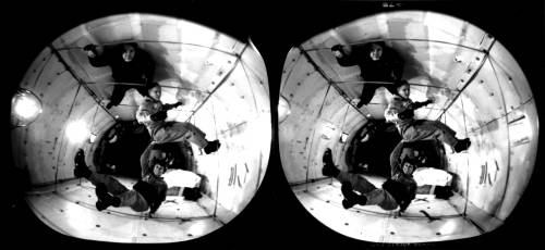
Figure 1: Example LEEPshot
Then Michael McGreevy and Scott Fisher at NASA AMES Research Center began using LEEP viewer lenses with LCDs in a display mounted on the head, with sensing of the head position so that a computer could create a stereo video rendering of a world in which the wearer would be immersed. That happened in 1985, and was the beginning of the present ferment that calls itself "Virtual Reality." Since then we have provided almost all of the lenses used in Virtual Reality headmounts and have also supplied complete systems of our own.
2.2. Finger Exercises
Lest there be any doubt about the fact that the eye normally sees a very wide angle, we have devised two simple finger exercises. The first (Fig. 2) involves wiggling your fingers at arm's length on opposite sides of the head, 180 degrees apart. Looking straight ahead, people with normal vision can see both fingers wiggling. If we add the capacity of the eyes to swivel approximately 90 degrees, we see that the entire field of view is in fact 270 degrees — entirely without the benefit of head motion.
Figure 2

Figure 3
The second finger exercise (Fig. 3) demonstrates the corneal field. The shaded area shows that region in which a wiggling finger is viewable by the right eye if the gaze is straight ahead. When the eye rotates to look at the tip of the nose, the wiggling finger vanishes, When looking through a hole (or lens) we can see farther to the side by looking straight ahead! The point is further illustrated in Fig. 4.
2.3. The Sharpness Sacrifice
A great many people find the lack of angular resolution provided by current head-mounted displays disappointing when they first look into one. Almost everybody, however, stops complaining and groping for the focus knob after a few minutes — after being told positively that it's not going to get any better. They forget about it and begin to enjoy the wide angle experience. The sacrifice in sharpness in going from photographs to LCDs is nevertheless a serious matter; for real work the poor resolution is the main disadvantage of current systems.
The LEEP format mapping into a fisheye-like image maintains as sharp an image as possible with a wide field and a single LCD per eye. Serious work, however, requires resolution improved by 1 or 2 orders of magnitude; such resolution will be available from LEEP in the very near future in the form of the dual resolution CYBERFACE, In this system we double up on the number of video channels in order to provide a high resolution insert for each eye. This means that a central region of the field of each eye will have an optical insert in the center of the field with as many pixels as the entire wide angle field. The center field insert may be from 5 to 30 degrees in width. In the range of 5 to 10 degrees, the resolution will actually approximate that of the human eye.
3. IN PURSUIT OF THE ULTIMATE WIDE FIELD
3.1. How Wide is Wide? — the Stereo Window
Before getting into descriptions of particular systems we should try some expression of what wide angle really is. Those untutored in the matter, and that means almost everybody at this date, tend to think of wide angle as something you see through 7 x 30 binoculars, or something that a 20 mm focal length lens provides on a 35 mm camera, or (and this is a bit closer to the mark) something that subtends a 60 degree field at your eye.
For Virtual Reality purposes, even a 60 degree field is not wide enough for a very simple reason: it's possible to see both sides of the field with both eyes simultaneously . Therefore, there is a left and right edge to the scene, and both edges are located at a particular distance from the viewer because they are seen in stereo with two eyes. This fact leads to the phenomenon called by stereo photographers the "stereo window". For them it's mostly a problem of how to mount the slides so that the location of the window, which can be anywhere from arm's length to infinity, is suitable for the subject matter. Sometimes you don't want the things you are looking at to be sticking through the window; other times it's preferable. The problem is thought mainly a nuisance attendant on mounting slides.
Figure 4
But for Virtual Reality, the difference is critical. When there is a stereo window there is no ignoring the fact: either you are looking through some sort of window onto the world, or the world has a distant frame around it. Neither of these effects is natural. Neither of these permits what NASA has aptly called the "feeling of immersion in a virtual world". Briefly put, if there is a stereo window, the observer is on the outside looking in. Only when the field of view is so wide that the stereo window vanishes, can the observer rightfully consider himself or herself on the inside of the world looking out and around. The angular field of view required to eliminate the windows is about 80 degrees, so any system that provides a field of view less than 80 degrees, in particular any system with an eye lens whose diameter is much less than about twice the distance from the lens to the center of the eyeball, is going to show a stereo window. Such a system fails in a critical way to qualify as immersive virtual reality.
Figure 5
The original LEEP system qualifies in that it provides at least a 90 degree field of view by most reasonable definitions (Fig. 5). There is the important proviso that the image presented to it must fill the lens. In actual cases, the LCD used is often too small. A 3 inch diagonal, for example, is too small, and therefore a 90 degree field of view, much less a 110 degree field of view cannot reasonably be claimed.
If a 4 inch diagonal LCD is used, the field of the lens is fully filled, though, depending on the aspect ratio, the vertical may be clipped a little. Under these conditions the horizontal field of view is determined only by the geometry of the eye/lens combination. The direct field equals the angle subtended at the eyeball center by the edge of the lens.
3.2. What is the Resolution?
Probably the most frequent question about head-mounted displays is, "What is the resolution?" Typically a computer user is asking the question, someone who finds (because monitors have a small range of diagonals — usually between 12 and 19 inches) that the x by y pixel count gives them some sense of whether or not the display will satisfy their eyes. The expected answer is something like "Six hundred forty by four eighty." Such an answer is almost meaningless when applied to head-mounted displays for Virtual Reality. There are several important reasons.
3.2.1. The Fields of View are of a Different Order.
A 14 inch diagonal monitor at the average viewing distance subtends an angle at the eye of about 30 degrees; if you sit back in your chair, your 12" monitor gives you only about 15 degrees! The latter is still a lot better than the typical TV viewing condition, which provides a field of about 5 to 10 degrees for normal group watching. Fig. 6
Figure 6: FOV Chart
(On a recent flight, while guessing at the dialogue of a Goldie Hawn movie, I determined that the screen width was one thumb at arm's length — that comes out to about two degrees! And I really wasn't objecting to the narrow view, just idly curious. It's worth noting that the resolution was exquisite, but the visual presence was nil: there was no sense of being there with Goldie!)
The table of Fig. 6 is intended to give a rough but realistic sense of the demands of virtual reality imaging. Note that a high quality (146 degree) VR image has about 40 times the solid angle of a desktop monitor. A million pixels may be beautiful on the monitor, but they won't go far in VR. To duplicate that monitor sharpness over the field would take about 40 times the bandwidth! Fortunately that's not necessary: because the eye is obliqingly unsharp over most of its field of view, maximum sharpness can be reserved for the center. Note that the last column is based on the assumption that the fovea can resolve 60 lines per degree.
3.2.2. There is Confusion About Counting Color Pixels.
In small LCDs the manufacturers tend to take the sum of the red and green and blue pixels when specifying resolution, whereas in larger displays white pixels (color triads) are counted. Even some manufacturers reps are confused, so it is necessary to be very demanding when asking verification of the numbers. (The difference in the horizontal direction may be a factor of 3 or 2 or i.5, depending on the layout of the color triad.) A convenient way to eliminate ambiguity is to ask for the red pixel pitch, horizontal and vertical. The following formula will permit accurate comparison of the angular resolution of various systems on the optical axis, where it is most important, (Manufacturer must supply data.)
3.3. Where is the Focus Knob?
Probably the most disconcerting fact arising out of the use of available LCD's at the magnification required for virtual reality is the large size of the resulting pixels. If they are sharply focused, they show up as large red, green and blue dots (almost all systems are color) that are so dramatic in their sharpness and color as to preempt the perception of any image that may lie behind them. The effect is reminiscent of that obtained by looking at a coarsely screened photograph with a powerful magnifier: at a certain point, all you see is dots. A number of ways of mitigating this effect have been used, none of which changes the fundamental resolution much, but all of which provide a degree of relief from those sharp colored dots. De-focusing, diffusion, and the interpolation of fine dot screens (high spatial frequency confabulation) — all can provide a subjectively improved visibility and clarity of the image behind the pixels. It is hard to say that any of these procedures is an improvement over simple de-focusing. De-focusing also has the advantage that it can be adjusted for personal taste; it has the disadvantage, however, that very near-sighted or far-sighted people, without their glasses, will see the imagery quite differently. The LEEP system puts the image about 5 diopters past infinity. This is not to say that there should not, in fact, be a focus knob. It has only recently become quite apparent that even the extreme de-focusing should be selectable by the user.
4. THE LEEP STANDARD
4.1. Principles for Wide Angle
Before attempting to introduce some precision into the matter of specifying field of view for head-mounted displays, we want to enunciate some principles that our decade-long familiarity with very wide angle stereo has made quite clear to us, but which we find is not at all clear to many persons who should be concerned.
Figure 7
4.1.1. LEEP Principle #1
Immersive stereo vision begins when you step through the stereo window. That is to say, when roughly speaking, the field of view is 80 degrees or more.
4.1.2. LEEP Principle #2
For a windowless, virtual world with maximum sharpness, it is necessary to do an anamorphic projection of the space — the so-called LEEP format. This point is illustrated in Fig. 7. Three cubes, side by side, are projected in two ways. At the left there is the LEEP format view, approximately like a fish-eye image. At the right is a linear projection such as might be provided by a very wide angle, but not fish-eye, camera lens, or for that matter, by a pin-hole camera. In each case the overall field of view is 140 degrees, which is approximately that of the CYBERFACE 2. Note that in order to render the imagery at the proper angles (this is the same as saying that you are showing the image life-size) it is necessary to magnify the linear image in the right frame almost 3 times as much at the center of the field. There are clear and important disadvantages to this extra magnification. First, a powerful magnifier is invariably a small magnifier, so that to see the entire field of view the eye must be moved back and forth to peer through a small lens. Such motion is not possible in a head-mounted display. Second, angular resolution or sharpness of the image presented to the eye is, and will be for a long time, dependent on the pixel pitch of the LCDs, or the spot size of the cathode ray tubes on which the image appears. Magnifying the image 3 times more than necessary immediately worsens the resolution by a factor of 3. If to compensate, we increase the resolution of the device by a factor of 3 (by wishing for it) we find that we have increased our bandwidth and storage requirements by a factor of 9. All of this could have been avoided by using appropriate anamorphic projection such as that shown at the left.
4.1.2. LEEP Principle #3
There should be no adjustment of the spacing of the optical axes (unless the eyelenses are very small, which would make them unsuitable for VR applications, and even then both the lenses and the LCDs would have to be moved). The spacing of the lenses is determined by, and only by, the spacing of the LCD images (though for practical reasons it should be a millimeter or two greater). Providing a user adjustment produces confusion and discomfort.
4.2. Proposed Field-of-View Standard
The field of view of very wide angle optics is not a simple number for a variety of reasons. A clear constraint is the size of the lens nearest the eye, the "eye lens". The LEEP eye lens has an edge radius of 30 millimeters and therefore limits what we call the "direct field of view" to 90 degrees if the center of rotation of the eye is on the optical axis (at a typical distance of) 30 millimeters from the center of the ocular (Fig. 5). An additional field, called the "corneal" field in LEEP literature, is sensed if the eye is looking straight ahead because of refraction of light at the corneal surface and because the pupil is significantly closer to the ocular than is the center of the eyeball. As the pupil moves closer to the eye lens, from 20 to 15 millimeters, the "corneal field" increases (from the geometry) from 112 degrees to 126 degrees. (Note that this "corneal field" is not available in all systems using LEEP optics because the LCDs used are often not large enough, with the result that the field of the lens is not properly filled.) If the eye is free to translate left and right (which is ordinarily not the case with head-mounted displays) an additional "peering" field may be visible up to the full 70 degrees off-axis recorded on the video field by the LEEP camera lenses.
In view of these many considerations, yet mindful of the need for some convenient comparison, we propose a two-number specification: the 20/33 field. The numbers denote the geometric direct field measured from the center of the eyeball when it is located at a distance of 20 and 33 mm from the center of the circle described by the edge of the eye lens (see again Fig. 5). Of course a complete plot of field vs. eye distance would be better, but we feel these two points will show the effects, respectively, of lens filling by the image field and of eye lens diameter, each measured at a practical distance. By this measure the LEEP standard optic (with 4" diagonal LCD) has a 20/33 field of view of 112.6/84.5 degrees.
5. COMPUTING THE ORTHOSPACE
5.1. The Projection Algorithm
Figure 8 makes the simplest statement of the requirement for LEEP projection on to the viewplane. The x-y-z coordinates represent any vertex in an object space in which the x-y plane is the viewplane and the z-axis is the viewing axis with the origin at the center of the eyeball. If a hemisphere having a radius equal to the focal length of the viewing optics (42mm in the LEEP case) is centered on this view plane, then the projection consists merely in determining the intersection of the hemisphere and a ray from the origin to any vertex, then dropping from this intersection perpendicularly to the viewplane.
Figure 8
An algebraic version of the computation is given. A trigonometric form or look-up table may also be computationally convenient.
Any straight line becomes a segment of an ellipse in the viewplane because the ends of the line and the origin determine a plane, the intersection of the plane and the hemisphere determines a great circle, and the projection of the great circle on to the viewplane must be an ellipse centered at the origin.
5.2. Modifying the Pipeline
Figure 9 shows a modification of a popular graphics pipeline. The double asterisks mark operations or components added especially to perform the LEEP Orthospace projection. Note particularly that the clipping is simplified by comparison with conventional linear projections because only one plane has to be considered — the viewplane itself.
Figure 9
5.3. Mapping Code from LEEP
LEEP Systems has developed code for performing the Orthospace projection, and we will make it available to selected customers on a beta test basis. The computational overhead that this code represents is modest enough that we believe it no longer tenable to tolerate non-Orthospace wide angle rendering with its numerous ill effects.
5.4. Telepresence Camera Lenses
When there is no computer involved, as in a telepresence system for roaming the surface of Mars or searching for sunken treasure, the mapping of the space is accomplished simply by using LEEP format camera lenses on the stereo video platform. The TELEHEAD (tm) shown in the photo of Fig. 10 is equipped with a pair of lenses that provide the LEEP Orthospace (tm) format so the video signal matches the CYBERFACE 2 optics both as to angular correspondence and axial divergence.
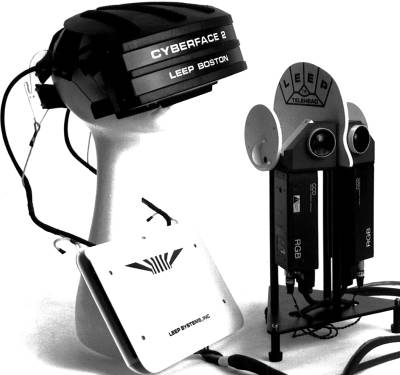
Figure 10
6. THE CYBERFACE 2
The field of view of the LEEP system is large enough that, with essentially the same optical design, the optical axes can be diverged by as much as 25 degrees without sensible loss of stereo overlap. The result is a distinct increase in the sense of wide field and a very useful increase in the room available to mount the LCDs.
The resulting LEEP "plus 25" optics have been incorporated in a virtual reality system called CYBERFACE 2 (Fig. 10). In the CYBERFACE 2 an additional 25 degrees of "total lateral field" (left extreme of left eye to right extreme of right eye) is captured by diverging the optical axes of the LEEP camera lenses (or the computer view axes, if that's where the signals originate) by 25 degrees to match the divergence in the head mount. As a result, the total perceivable lateral field can be as much as 165 degrees, though in a normal head-mounted arrangement this much field is not visible at once. Because the eyeball cannot move, except to rotate, with respect to the lenses, the field of view is normally limited by the edge of the eye lenses by the size of the "hole" through which one has to look.
7. THE DUAL RESOLUTION CYBERFACE
7.1. Parameters of the Dual Resolution CYBERFACE
The angular resolution, or sharpness of viewed detail, in the CYBERFACE 2 is unsatisfactory for most real applications. This is true of all LCD-based head-mounted wide angle displays because there are nowhere near enough pixels in any available or foreseeable LCD to permit the wearer to do detailed work: wide angle calls for great magnification of the pixel plane; good resolution calls for minimum magnification. While the LEEP format mapping embodied in the CYBERFACE 2 makes the best of a difficult compromise (Fig. 7) it is still not good enough to qualify as a serious tool. The Dual Resolution system with four video channels decisively overcomes this limitation, and promises to be the precursor of all successful Virtual Reality display hardware.
In the Dual Resolution CYBERFACE, an area near the center of the visual field, the "insert", will be displayed with vastly more detail than is seen elsewhere. This arrangement will enable the wearer to bring a selected part of the visual field into sharp relief simply by turning his or her head, without losing track of the surrounding world. The generation of the inserts, and their subsequent combining into a composite field, is done optically, so there is no limit on the central acuity imposed by electronics or by pixel size: the smaller the insert, the higher the insert resolution will be. The best size for the inserts is still to be determined experimentally, though it is expected to fall in the range of 10 to 30 degrees. Also to be determined is whether the inserts will in fact be of the same size or whether there will be one high resolution insert (20 to 30 degrees) and one very high resolution insert (5 to 15 degrees). It is our expectation that the different sizes will make good use of the great capacity of the brain to attend to the better of two images presented to the eyes, and largely to ignore the other.
Figure 11: Optical Schematic of Dual Resolution Display
The use of different size inserts also eliminates the question of where in space to locate a possible high resolution "window"; if both close and distant viewing is needed, having equal small inserts would entail moving one of them to match a changing convergence angle of the eye axes. It should be added here that we have observed, when one image is markedly sharper, that neither the stereo sense nor the perception of sharpness is noticeably affected by the lack of sharpness in the second image. Finally, because the most desirable dimensions of the insert may vary with different applications, it is possible that the finished units will have an adjustable, or at least a modifiable, insert size. As presently planned, the wide angle field will be presented on a super twist LCD, either monochrome or having composite color inputs, having the same field as the CYBERFACE 2. The high resolution insert will use active matrix color with RGB plus sync inputs or composite video, PAL or NTSC.
7.2. Optical Geometry of the System
The optical schematic of Fig. 11 shows the 140 degree "eye" of the camera, which is essentially an afocal field element. Two video cameras are aimed at the back of this element through a half reflecting mirror. One of the cameras comprehends the entire afocal element, giving a normal LEEP format. The other camera operates at higher magnification to pick out only the central part of the image. The two video channels lead to two LCDs in the head-mounted display, whose images are combined optically at a single plane for magnification and linear reconstruction by the LEEP viewing optics.
7.3. System Packaging
Figure 12 shows one packaging of the Dual Resolution CYBERFACE. The two extra LCDs and associated optics are located either to the side or to the top of the head. The resulting assemblage is bulky, but it incorporates readily available LCDs that are known quantities and very reliable. Smaller LCDs are planned for future systems. The greater weight of the unit in comparison with the CYBERFACE 2 will not cause significant discomfort because it is offset by a new LEEP counterpoise, which makes it possible to remove all uncomfortable forces from the face.
Figure 13 shows the configuration of the four cameras on the dual resolution TELEHEAD. Here, too, we use readily available components that are known quantities and very reliable. A more compact head is certainly possible using tiny cameras currently available, but compactness of the TELEHEAD is not part of the working set of design desiderata.
Figure 12
Figure 13
8. BIBLIOGRAPHY
Early 1980s
- Spooner, A. Michael The Trend Towards Area of Interest Displays in Visual Simulation Technology Naval Training Equipment Center, Orlando, FL, 1982.
- Howlett, Eric M. U.S. Patent Number 4406532 Wide Angle Color Photography Method and System September 27, 1983.
- Howlett, Eric M. POP-OPTIX LABS How Aberrations of the Film Image are Used to Neutralize Lateral Color and Distortion in the Magnifiers of the LEEP (tm) System of Ultra Wide Angle Stereophotography 37th Annual Conference of the Society of Photographic Scientists and Engineers, Boston May 20–24, 1984.
- Oman, Charles M. et. al. Etiological Mechanisms of Space Motion Sickness Proposal to NASA from the M.I.T. Center for Space Research, October 1, 1984.
From the Conference on "Real-Time Stereoscopic Video Display Systems", Bedford, Massachusetts, March 22–24, 1987
- Haas, Gary U.S. Army Field Telerobotics U.S. Army Engineering Lab.
- Howlett, Eric M. Very Wide Angle Stereoscopy Ultravision Technology. Corporation.
- Spain, E. Hugh Telepresence with Stereoscopic TV Displays Naval Ocean Systems Center, Hawaii Laboratory.
- Welch, Brian A Fibre Optic Helmet-Mounted Display CAE Electronics Ltd.
From the 1987 Image Conference Number 4, 26 June 1987, Phoenix Arizona
- Fisher, Robert and H. M. Tong. A Full Field of View Dome Visual Display for Tactical Combat Training The Singer Company, Link Flight Simulation Division.
- Roberts, Malcomb and Paul Murray. Required Performance for an 'Area of Interest' System for Operation Training Rediffusion Simulation, Crawley, England.
- Barber, Bruce et. al. AOI Displays for Operational Training Rediffusion Simulation.
- Williams, Terrance, CAE Electronics and M. Komoda, Concordia University and J Zeezi, Technion Institute. Techniques and Methods Used in Eye Tracking in the Fiber-Optic, Helmet-Mounted Display.
- Hettinger, Lawrence. Human Performance Issues in the Evaluation of a Helmet-Mounted Area-of-Interest Projector Essex Corporation.
From the Conference on "Real-Time Stereoscopic Video Display Systems For Telerobotics, CAD/CAM & Medical Imaging", Bedford, Massachusetts, March 20–22, 1988
- Fisher, Scott S. Virtual Environment Display Systems NASA Ames Research Center.
- Howlett, Eric M. Very Wide Angle Stereoscopy Pop-Optix Labs.
- McGovern, Douglas E. Human Interfaces in Remote Driving Sandia National Laboratories.
- Merritt, John O. Overview of Real-Time Stereoscopic Video Display Applications Interactive Technologies.
More Recent
- Howlett, Eric M. Wide Angle Orthostereo SPIE conference proceedings, Santa Clara, CA, Feb.1990.
- Howlett, Eric M. Virtual Reality — A Brand New Medium, Address to the Boston Computer Society, September 1990
- Howlett, Eric M. Orthospace Rendering with Various Computer Platforms, Presentation at the SPIE Conference on Display Technology, San Jose, February 1991.
- Howlett, Eric M. The Reality of Virtual Reality, Dinner address for the Association for Women in Computing, Boston, March 19, 1991.
- Howlett, Eric M. Virtual Reality, Conference Panel, Electronic Imaging International, Society for Information Display, Boston, October 1991.